Shopping Cart
0 item(s) - R0.00-
- - Amplifier Module
- - Arduino Compatible - Development Platform
- - Arduino Compatible Modules & Shields
- - Breakout Boards
- - Cables / Hookup wires
- - Displays
- - Enclosures
- - Magnets
- - Motors & Gears
- - Nuts & Bolts
- - Peltier Cooler Heater
- - PIR
- - Sensors
- - Servo's & Motors
- - Solar
- - Stand Alone Modules
- - Stepper Motor & Drivers
- - USB Programmers & Converters
- - Voltage Regulator & Chargers
- - RC Hobby Parts
-
- - AC DC Cooling Fans
- - Cable Ties
- - Day/Night Switches
- - Electrical Plugs & Connectors
- - Gate Remotes & Receivers (Universal)
- - Heat Shrink Sleeves
- - Insulation Tape
- - Lighting & Globes
- - Mains Power Cables
- - Power Supplies & AC/DC Adaptors
- - Security Lights LED Type
- - Solar Charge Controllers
- - Surge Protectors
- - Timers
-
- - Battery Holders
- - Breadboard
- - Bridge Rectifier
- - Buzzers
- - Capacitors
- - Crystals
- - Diodes
- - Electromechanical
- - Fuses
- - Headers
- - Heat Sinks
- - IC Sockets HQ
- - IC Sockets TIN
- - IC's --> Semiconductor
- - Inductors
- - Laser Units (CD Players)
- - Microcontrollers & CPU's
- - Opto Electronics
- - Panel Meters And Displays
- - Passive Components
- - Pilot Lamps & Fittings
- - Plugs & Sockets
- - Resistors
- - Rotary Potentiometer
- - Semiconductors
- - Sensors
- - Switches
- - Transformers
- - TVS Diodes
- - Veroboard / Stripboard
- - Voltage Regulators
- - Zener Diode
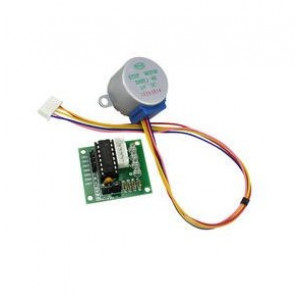
Motor Stepper 5V DC 4 Phase & ULN2003 Driver Board A23+A24
Availability: ETA 30 Days ETA (please call)
Ex Vat: R69.57
Add to Compare
Stepper Motor 5V DC 4 Phase & ULN2003 Driver Board A23+A24
1 x 5 Volt Unipolar Stepper motor
1 x ULN2003 Stepper Motor Driver Board
Stepper motor with step angle of 5.625° mainly used in Air Conditioner LouverS, Small Cooling/Heating Fan etc.
Bullet Points:
1 piece x 5V Unipolar Stepper motor with ULN2003 Board
Voltage: DC 5V
Step Angle: 5.625 x 1/64
Stride Angle : 5.625° /64
Reduction Ratio: 1/64
Number of Phases : 4
Specifications for Stepper Motor:
Voltage: DC 5V
Diameter: 25mm
Step Angle: 5.625 x 1/64
Reduction Ratio: 1/64
Rated voltage : 5VDC
Number of Phases : 4
Speed Variation Ratio : 1/64
Stride Angle : 5.625° /64
Frequency : 100Hz
DC resistance : 50O±7%(25?)
Idle In-traction Frequency : > 600Hz
Idle Out-traction Frequency : > 1000Hz
In-traction Torque >34.3mN.m(120Hz)
Self-positioning Torque >34.3mN.m
Friction torque : 600-1200 gf.cm
Pull in torque : 300 gf.cm
Insulated resistance >10MO(500V)
Insulated electricity power :600VAC/1mA/1s
Insulation grade :A
Rise in Temperature <40K(120Hz
Noise <35dB(120Hz,No load,10cm)
Model : 28BYJ-48
Features of ULN2003 BASED Stepper motor driver board:
ULN2003 Stepper Motor Driver Board is compact
It uses the ULN2003 driver chip to amplify the control signal from the Arduino and other MCU used.
It uses the ULN2003 DARLINGTON ARRAYS to drive the 4-phase 5-wire stepper motor ( 5v to 12v ).
Compatible with Arduino or other development platform to drive the stepper motor.
More Features:
4-way signal indicator
All the pins have Input leads Mounted for easy connection to use
XH-5P socket can be connected directly 28BYJ-48 Model stepper motor
A. B. C. D LED indicating the four phase stepper motor working condition.
White jack is the four phase stepper motor standard jack.
Power pins are separated
Other Specifications:
Dimensions: 32 x 18 x 11mm (LxWxH)
How to Control Stepper:-
The stepper motor is used to convert pulse to angular displacement. So if you give the stepper driver a certain pulse signal, it will drive the stepper motor to a certain angle. you can control the angle of the stepper motor by adjusting the number of pulses. And you also can control the speed of the stepper rotation by the frequency of the pulse.
Connections:
IN1-4 to the Microcontroller Pins
The pins in the white jack (from left to the right) are: VCC, A, B, C, D (to the stepper motor)
Power pins are on the right, use jumper to choose either 5V or 12V.
Write a review
Your Name:Your Review: Note: HTML is not translated!
Rating: Bad Good
Enter the code in the box below:


-80x80.jpg)


